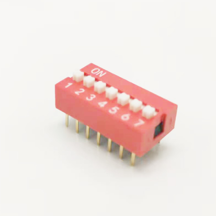
DIP switches are compact manual electronic switches with a standard dual in-line package design. They mount directly on PCB boards for hardware parameter configuration. For industrial equipment and control cabinet design, DIP switches serve as a more stable and reliable alternative to traditional jumper blocks.
Unlike jumper caps that are easy to loose or misplace during on-site wiring, DIP switches offer semi-permanent, tool-free configuration. They simplify hardware setup and effectively reduce hidden faults in long-term equipment operation, which is why they are widely used in industrial control and electronic device design.
Three Common Types of Industrial DIP Switches
Different DIP switch structures fit distinct PCB installation positions and on-site operation scenarios. Professional manufacturers provide three mainstream styles to match diverse equipment shell and layout designs:
1. Slide Type DIP Switch
This is the most widely used DIP switch in industrial projects. Engineers toggle a small top slider back and forth to turn circuits on or off.
It features a sturdy structure with clear visual on/off status. Field staff can quickly check configuration states at a glance without professional testing tools, making it ideal for conventional PCB top-mounted layouts.
2. Piano Type DIP Switch
Piano-style DIP switches have side-mounted keys instead of top sliders, similar to piano keys. This structural design solves a common on-site installation problem.
When PCBs are installed at the edge of equipment or limited by narrow device enclosures, top operation is impossible. Piano-type switches allow side operation, perfectly adapting to edge-mounted PCB layouts with space limitations.
3. Rotary Type DIP Switch
Rotary DIP switches abandon traditional independent sliders. They adopt a tiny rotating dial that aligns with specific hexadecimal or binary values.
This type is highly targeted for parameter setting. It is the preferred choice for configuring equipment addresses, communication channels and fixed coding parameters in industrial control systems.
DIP Switch Types Comparison Table
This intuitive comparison helps design and procurement engineers quickly select the right DIP switch for different project requirements:
DIP Switch Type
Core Features
On-Site Advantages
Best Application Scenarios
Slide Type
Top sliding operation, clear on/off visual indication, durable structure
Easy inspection, low failure rate, universal compatibility
Standard top-mounted PCBs, general industrial control equipment
Piano Type
Side key operation, no top operating space required
Solves enclosure space limitation problems, flexible installation
Edge-mounted PCBs, compact devices with narrow internal space
Rotary Type
Rotary dial positioning, supports hex/binary coding
Accurate parameter setting, no configuration deviation
Equipment address setting, channel coding, communication parameter configuration
Key Practical Benefits of Using DIP Switches
1. Lower Equipment Design Costs
Many low-power industrial devices only need simple fixed parameter configuration. Adding display screens or extra microcontroller interfaces for basic settings will greatly increase production costs.
DIP switches support direct hardware configuration with zero auxiliary circuits. It is the most cost-effective solution for mass-produced standard equipment.
2. Power-Down Configuration Memory
Software-based parameter settings rely on backup batteries to save data. Battery aging or power failure will cause parameter loss and equipment operation errors.
DIP switches adopt physical mechanical positioning. The configured state remains stable permanently, regardless of power outages or equipment restarts. It avoids repeated debugging work for on-site engineers.
3. Higher Hardware Security
Software parameters face risks of remote tampering, program crashes and system bugs. These hidden dangers may lead to abnormal equipment operation.
DIP switch settings are completed through physical hardware. They cannot be hacked or modified by software failures, ensuring stable and safe equipment operating parameters.
Common Industrial Application Scenarios
DIP switches (including standard 8-bit SMD and DIP models) are standard accessories for various electronic and industrial control devices:
- Industrial Control Systems: Set PLC Modbus addresses, baud rates and communication parameters
- Computer Peripheral Hardware: Configure motherboard parameters, expansion card functions and arcade board logic settings
RF & Wireless Devices: Adjust operating frequencies and channels for garage door openers, industrial radio transmitters
Practical DIP Switch Selection Guide for Engineers
Based on on-site PCB production and equipment maintenance experience, confirm three core indicators before purchasing DIP switches:
1. Number of Positions
Confirm the required configuration bits according to your circuit design. Standard industrial DIP switches range from 1-bit to 12-bit. Reserve 1-2 spare bits appropriately for subsequent equipment function upgrades to avoid secondary board modification.
2. Mounting Method
Match the mounting type with your production process. Through-hole DIP mounting fits traditional plug-in welding processes. Low-profile SMD surface mount models are suitable for automated SMT production lines and ultra-compact PCB layouts.
3. Waterproof and Cleanable Grade
If your PCBs need to pass automatic cleaning processes after welding, ordinary DIP switches will have flux and cleaning solvent residue entering the internal structure, causing poor contact.
Choose sealed cleanable DIP switches with polyimide tape protection. The protective tape blocks impurities during cleaning and can be torn off after processing, ensuring long-term switch stability.
FAQ for Industrial DIP Switches
Q1: What does pitch mean for DIP switches?
Pitch refers to the center-to-center distance between adjacent pins. The industry standard pitch is 2.54mm (0.1 inch), compatible with most universal PCB layouts. For ultra-compact mini devices, 1.27mm half-pitch models are available to save board space.
Q2: Can I clean PCBs with mounted DIP switches?
Yes, but only for sealed and cleanable-grade DIP switches. These switches come with temporary protective tape on the sliders, which prevents flux, dust and cleaning solvent from entering the internal mechanical structure. Just peel off the tape after the PCB cleaning process is finished.
Q3: What is the service life of industrial DIP switches?
DIP switches are designed for fixed hardware configuration, not frequent daily operation. Their mechanical service life is rated at 1,000 to 2,000 operations. This lifespan is completely sufficient for equipment debugging, installation and routine maintenance throughout the equipment life cycle.
Q4: Which is better, slide type or piano type DIP switch?
It depends on your PCB installation position. Slide-type switches are better for top-mounted PCBs with operating space, offering intuitive status checking. Piano-type switches are the only choice for edge-mounted PCBs or equipment with blocked top space, with no performance difference in service life and stability.
Q5: Are rotary DIP switches necessary for industrial control projects?
Rotary DIP switches are specially used for address coding and channel setting. Compared with slide switches, they provide more accurate digital positioning and avoid configuration errors. They are highly recommended for multi-device parallel industrial control systems that require unified address management.
As electronic systems grow more sophisticated, managing dozens of wire-to-board and board-to-board connections can quickly turn into a messy logistics problem for cabinet integrators. MCS, short for Multi Connection System, delivers a standardized, highly flexible way to handle industrial wiring. This article explains how adopting an MCS architecture can reshape your product design workflow and reduce on-site wiring risks.
What Are MCS Terminal Blocks?
MCS stands for Multi Connection System. It is not a single standalone connector. Instead, it is a full family of interoperable connectors built under one unified framework. The system handles mixed power and signal circuits seamlessly.
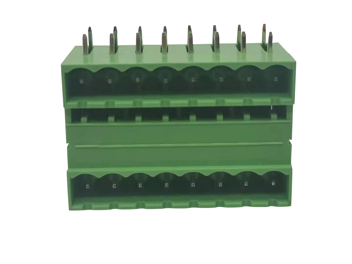
MCS pluggable PCB terminals offer great flexibility. Using one consistent design platform, engineers can implement wire-to-board, wire-to-wire, and board-to-board connections across the whole equipment.
Core Advantages of MCS Architecture
1. Extreme Modularity
Standard MCS systems allow engineers to freely mix headers and mating plugs.
If you need to upgrade or modify one section of a machine, you only adjust that local module. There is no requirement to redesign the entire wiring harness. This cuts redesign cycles and saves lots of rework during prototype iterations.
2. High Density & Compact Footprint
PCB real estate inside control cabinets is always limited.
High-density MCS terminals use smaller pitch sizes while maintaining reliable electrical isolation. You can fit more signal lines and power circuits onto a smaller PCB without crosstalk or insulation risks.
3. Built-In Coding to Prevent Mismating
In dense control panels, plugging a cable into the wrong port can cause equipment damage or system downtime during commissioning.
Most MCS units come with configurable coding pins. This mechanical interlock only lets technicians plug connectors into their matching headers. It eliminates human wiring errors that often show up during site startup.
MCS Terminal Blocks vs Regular Pluggable Terminal Blocks
Feature
MCS Terminal Block System
Standard Separate Pluggable Terminal Pairs
System Scope
Full interoperable connector family with supporting accessories
Independent plug-header pairs with no unified ecosystem
Connection Types Supported
Wire-to-board, wire-to-wire, board-to-board
Mostly wire-to-board only
Anti-Mismate Feature
Custom mechanical coding pins available
Basic or no keying in most models
Modular Upgrade
Partial module modification without full harness redesign
Changes often require complete wiring rework
Scalability
Expand easily across multiple device variants
Hard to standardize across different product lines
Key Applications for MCS Connectors
Thanks to its flexible design, MCS wire-to-board connectors are widely used in high-reliability industrial systems:
Rail Transit: Control systems that demand stable, error-proof and modular connections
Building Automation: Complex HVAC controllers and smart building central hubs
Medical Devices: Modular equipment requiring frequent module replacement for maintenance or upgrades
Industrial Automation: High-density I/O modules and PLC expansion units
How to Select the Right MCS Solution
When you source MCS terminal blocks from manufacturers, verify these key specifications first:
1. Pitch Options: Common pitches include 3.5mm, 3.81mm, 5.0mm and 7.5mm. Match your selection based on working voltage and available PCB space.
2. Connection Technology: Modern MCS systems support both traditional screw clamping and fast push-in spring connections to fit different assembly workflows.
3. Locking Mechanism: For high-vibration environments, choose snap latches, screw flanges or lever locks to keep connections secure and prevent accidental disconnection.
FAQ for MCS Terminal Blocks
Q1: What is the difference between MCS terminal blocks and regular pluggable terminal blocks?
A: Ordinary pluggable terminals are just isolated plug and header pairs. MCS is a complete system. It includes matching accessories, multiple connection formats, and advanced anti-mismate features. All components work together consistently across your whole project.
Q2: Can MCS connectors carry both signal and power at the same time?
A: Yes. The Multi Connection System is engineered for mixed signal and power routing. By selecting the right pitch and contact material, you can safely run low-voltage data traces next to higher-power power lines on the same PCB.
Q3: Are MCS terminal blocks compatible with automated SMT assembly?
A: Absolutely. Many MCS pluggable PCB terminals come in tape-and-reel packaging. They use high-temperature resistant plastic, so they can go through standard SMT reflow soldering for high-volume automated production.
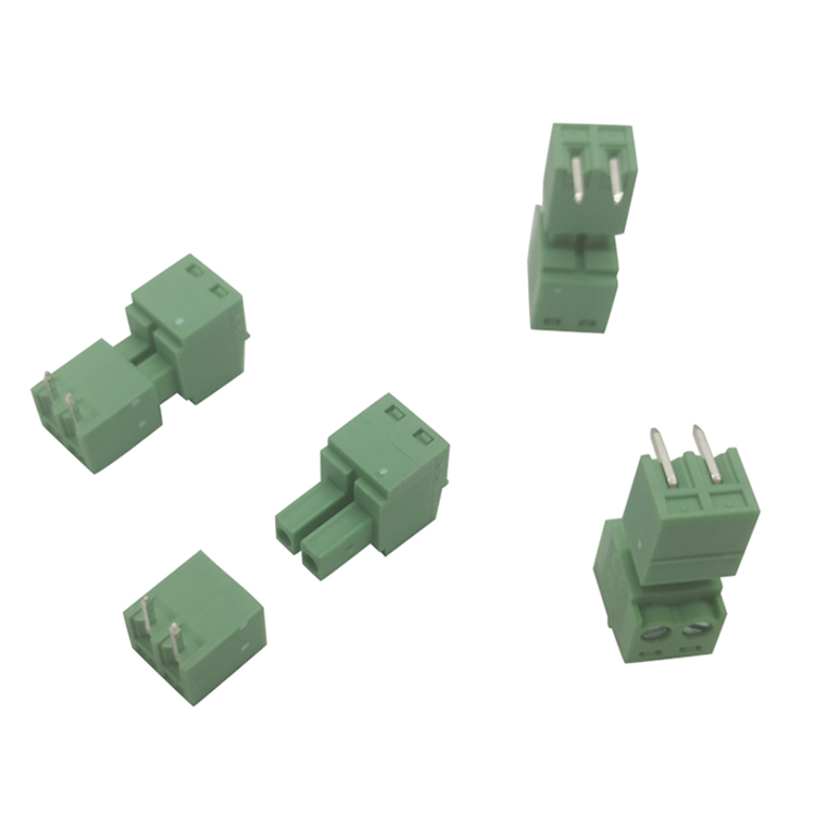
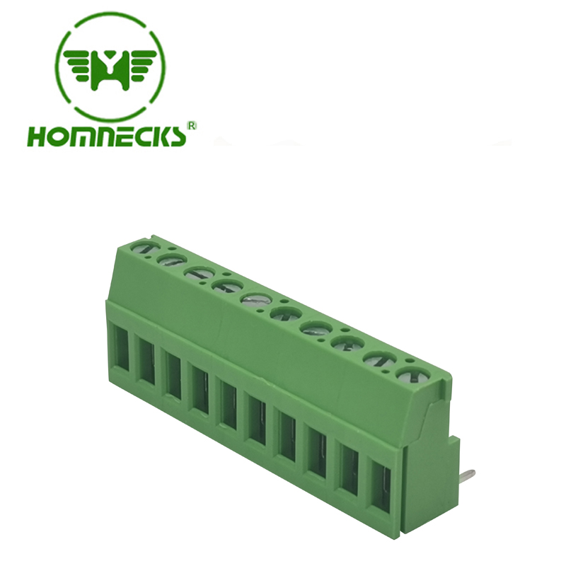
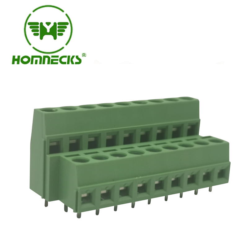
The solder pin design of screw terminals is usually divided into two types: straight pin and bent pin (Bent Pin or Right-Angle Pin). These two designs differ in installation method, space occupation and application scenarios. Here are their detailed differences:
1. Installation direction
Straight pin: The solder pin extends in a straight line with the terminal body and is installed perpendicular to the PCB (printed circuit board).
Bent pin: The solder pin is bent 90 degrees at the end and installed parallel to the PCB.
2. Space occupation
Straight pin: Since the solder pin is inserted vertically into the PCB, the terminal body will occupy the vertical space above the PCB.
Applicable scenarios: Suitable for applications with sufficient space above the PCB.
Bent pin: The solder pin is parallel to the PCB, and the terminal body is parallel to the PCB, occupying less vertical space.
Applicable scenarios: Suitable for applications with limited space above the PCB.
3. Installation method
Straight pin: The solder pin needs to be inserted vertically into the via hole of the PCB, usually used for through-hole technology (THT).
Bent pin: The solder pin can be directly soldered on the surface of the PCB, suitable for surface mount technology (SMT) or through-hole technology.
4. Mechanical strength
Straight pin: Since the solder pin is inserted vertically into the PCB, it has high mechanical strength and can withstand large tension and vibration.
Applicable scenarios: Suitable for applications that require high mechanical strength, such as industrial equipment or automotive electronics.
Bent pin: The solder pin is connected parallel to the PCB, and the mechanical strength is relatively low, but it can still meet most application requirements under reasonable design.
Applicable scenarios: Suitable for occasions where mechanical strength is not required, such as consumer electronics.
5. Soldering process
Straight pin: Usually wave soldering or manual soldering is used, which is suitable for through-hole insertion technology.
Bent pin: Reflow soldering (for SMT) or wave soldering (for THT) can be used, and the soldering process selection is more flexible.
6. Heat dissipation performance
Straight pin: The solder pin is inserted vertically into the PCB, the heat dissipation path is short, and the heat dissipation performance is better.
Bent pin: The solder pin is parallel to the PCB, the heat dissipation path is long, and the heat dissipation performance is slightly worse, but the heat dissipation can be optimized through PCB design.
7. Electrical performance
Straight pin: Since the solder pin is directly inserted into the terminal block 6 pole, the electrical connection path is shorter and the resistance is lower, which is suitable for high current applications.
Bent pin: The electrical connection path is slightly longer, which may increase a small amount of resistance, but the impact can be ignored in most applications.
8. Application scenarios
Straight pin:
Industrial control equipment
Automotive electronics
Power supply equipment
High vibration environment
Bent pin:
Consumer electronics (such as TVs, audio)
Communication equipment
PCB design with limited space
9. Cost
Straight pins: Usually have lower costs because of their simple structure and mature production process.
Bent pins: May have slightly higher costs due to the need for additional bending processing.
10. Design flexibility
Straight pins: The design is relatively fixed and suitable for standardized applications.
Bent pins: The design is more flexible and the solder foot direction can be adjusted according to the PCB layout, which is suitable for high-density PCB design.
Summary
Characteristics Straight Pin Bent Pin
Installation Direction Vertical PCB Parallel PCB
Space Occupancy Occupies vertical space Saves vertical space
Mechanical Strength Higher Lower
Soldering Process Wave Soldering, Manual Soldering Reflow Soldering, Wave Soldering
Heat Dissipation Better Slightly Worse
Electrical Performance Smaller Resistance Slightly Larger Resistance
Application Scenarios Industrial, Automotive, High Vibration Environment Consumer Electronics, Communication Equipment, Space-Constrained Design
Cost Lower Higher
Design Flexibility Lower Higher
Choosing a straight pin or a bent pin depends on the specific application requirements, including space constraints, mechanical strength, heat dissipation requirements, and cost.
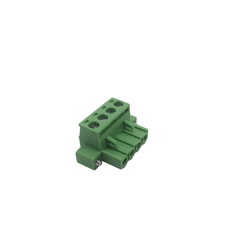
Plug in terminal blocks, as a common electrical connection device, are widely used in fields such as industrial control, power systems, and communication equipment. Its convenient installation and maintenance make it an important component in electrical connections. However, there are a wide variety of plug-in Terminal Block 4 Pin on the market with uneven quality. How to choose the appropriate 4 pin terminal block connector has become an important issue for users. This article will provide a detailed analysis of the key points for selecting plug-in terminal blocks from multiple perspectives, helping users make informed choices.
1、 Clear requirements
1. Application scenarios
1.1 Industrial Control
High reliability: Industrial control environments are complex and require wiring terminals with high reliability and stability.
Vibration resistance: Industrial equipment often experiences vibration, so it is necessary to choose 4 way terminal block with good seismic performance.
1.2 Power System
High current: In power systems where the current is high, it is necessary to choose wiring terminals that can withstand high currents.
High temperature resistance: When power equipment operates at high temperatures, high temperature resistant materials should be selected.
1.3 Communication equipment
High density connection: Communication equipment requires high-density connection and compact terminal blocks should be selected.
Signal transmission: Communication equipment has high requirements for signal transmission and requires the selection of low resistance and 4 way connector block.
2. Electrical parameters
2.1 Rated voltage
Voltage level: Select the appropriate rated voltage according to the actual application scenario to ensure that the wiring terminals can withstand the working voltage.
2.2 Rated current
Current capacity: Select the appropriate rated current based on the load current to avoid heating and damage caused by overload.
2.3 Insulation resistance
Insulation performance: Choose wiring terminals with high insulation resistance to ensure electrical safety.
3. Mechanical parameters
3.1 Number of insertions and removals
Durability: Select the wiring terminals with the highest number of insertions and removals based on their frequency of use to ensure long-term reliability.
3.2 Insertion and extraction force
Convenient operation: Choose wiring terminals with moderate insertion and removal force to ensure ease of installation and disassembly.
3.3 Seismic performance
Environmental adaptability: In vibration environments, choose 6 pole terminal block with good seismic performance to prevent loosening.
2、 Material selection
1. Conductive materials
1.1 High purity copper
Conductivity: High purity copper has good conductivity, reducing resistance and heat generation.
Mechanical strength: High purity copper has high mechanical strength, ensuring the stability of the connection.
1.2 Surface treatment
Coating quality: Choose conductive materials plated with tin or silver to improve corrosion resistance and welding performance.
2. Insulation materials
2.1 High temperature resistant materials
Heat resistance: Choose engineering plastics that are resistant to high temperatures, such as nylon, polycarbonate, etc., to adapt to high temperature environments.
Flame retardancy: Choose flame-retardant materials to improve safety.
2.2 Mechanical strength
Impact resistance: Choose insulation materials with high mechanical strength to prevent damage caused by external forces.
3、Brand and Quality
1. Brand selection
1.1 Famous Brands
Credit guarantee: Choose well-known brand terminal block 4 way, with guaranteed quality and after-sales service.
Market reputation: Refer to market reputation and user evaluations to choose brands with good reputation.
2. Quality certification
2.1 Certification Standards
International certification: Choose wiring terminals that have passed international certifications (such as UL, CE, RoHS) to ensure quality and environmental performance.
Industry standards: Wiring terminals that comply with industry standards (such as IEC, GB) to ensure compatibility and reliability.
3. Supplier selection
3.1 Regular channels
Authorized dealer: Purchase through legitimate channels to avoid counterfeit and inferior products.
After sales service: Choose suppliers who provide comprehensive after-sales service to ensure follow-up support.
4、 Price and cost-effectiveness
1. Price comparison
1.1 Market research
Multiple comparisons: Conduct market research to compare prices of different brands and models.
2. Cost effectiveness evaluation
2.1 Performance and Price
Comprehensive evaluation: Taking into account performance, quality, and price, choose products with high cost-effectiveness.
Long term cost: Consider long-term usage costs and choose products that are durable and have low maintenance costs.
The power industry is changing quite rapidly.And this is due to advancements in technology and the requirement for more efficient electrical systems.One of the significant aspects that are influencing this change are screw-type terminal blocks.These terminal blocks,actually,are extremely crucial as they ensure the connections are both secure and reliable.Their versatility and robustness make them essential in numerous applications,such as from industrial automation to renewable energy systems.Screw-type terminal blocks are rather important since they provide stable connections which are safe and dependable.As the power industry continues to evolve,these components still remain very important as they can accommodate different needs.They are widely used in various fields,including industrial automation and renewable energy systems,where reliability is of utmost importance.
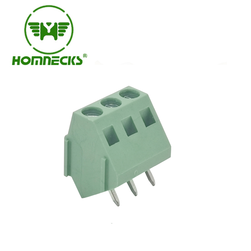
One of the most significant trends,is that there is a growing demand for terminal block 3 pole configurations.These blocks,are quite ideal for handling three-phase power systems,which are widely used in industrial and commercial settings.As the power industry moves towards higher efficiency and sustainability,the adoption of 3 pole terminal block solutions,is expected to increase,especially in solar and wind energy installations.
Another trend isthe integration of screw type terminal blocks with advanced PCB designs.The use of PCB barrier terminal block components allows forcompact and organized wiring,reducing the risk of short circuits and improving overall system reliability.This is especially important in modern power systems,where space optimization and safety are top priorities.
Besides multi-pole configurations,the need for more straightforward connections like the 2 pin screw terminal is increasing.These blocks,commonly utilized in low-voltage applications,are prized for their simple installation and maintenance.The 2 pin screw terminal block connector is especially favored in residential and small-scale commercial projects;it's a fact that where simplicity and cost-efficiency hold great importance.
The power industry is also seeing a shift toward more robust and environmentally friendly materials in screw type terminal blocks.Manufacturers are increasingly using high-quality,corrosion-resistant alloys and insulating materials that can withstand harsh conditions.This ensures that terminal block 3 pole and other configurations remain reliable even in extreme environments,such as offshore wind farms or high-temperature industrial facilities.
Looking ahead,the future of screw type terminal blocks in the power industry will be shaped by innovation and adaptability.From PCB barrier terminal block designs to versatile 2 pin screw terminal solutions,these components will continue to evolve to meet the demands of modern electrical systems.As the industry embraces smarter grids and renewable energy,screw type terminal blocks will remain a cornerstone of efficient and reliable power distribution.
By staying ahead of these trends,manufacturers and engineers can ensure that their systems are equipped to handle the challenges and opportunities of the future.Whether it’s a 3 pole terminal block for industrial applications or a 2 pin screw terminal block connector for residential usethe right terminal block solution can make all the difference.
When working with terminal block connector PCB components,one common challenge is ensuring that the plug and pin align perfectly.A mismatch can lead to poor electrical connections,increased resistance,and even system failures.Whether you're dealing with terminal block electrical connector systems or PCB pin terminal setups,addressing this issue is crucial for maintaining optimal performance.
The first step in resolving a mismatch is to verify the specifications of your PCB terminal connectors.Often,the problem arises from using incompatible components.Check the datasheets for both the plug and pin to ensure they share the same dimensions,pitch,and current ratings.If the PCB terminal blocks you’re using don’t match the pins,consider switching to a compatible model or consulting the manufacturer for guidance.
Another effective solution is to inspect the physical condition of the screw terminal block connector and its pins.Over time,wear and tear can cause deformation or corrosion,leading to alignment issues.Clean the contacts thoroughly and check for any signs of damage.If the pins or connectors are bent or worn outreplacing them with high-quality terminal block connector PCB components can restore proper functionality.
For those designing custom PCB layouts,double-check,the pin spacing and alignment during the design phase.A small error,in the layout of PCB terminal connectors can lead to a significant mismatch.Use CAD tools to simulate the connection and make sure that the PCB pin terminal aligns precisely with the plug.This proactive approach can save both time and resources during assembly.
If the mismatch persists,consider using adapters or intermediary connectors.Many terminal block electrical connector systems offer adapters that can bridge the gap between mismatched components.These adapters are particularly useful when integrating older PCB terminal blocks with newer systems or when working with non-standard pin configurations.
Finally,always test the connection after resolving the mismatch.Use a multimeter to verify the electrical continuity and ensure there’s no excessive resistance.Whether you’re working with screw terminal block connector systems or other types of PCB terminal connectors,thorough testing guarantees a reliable and long-lasting connection.
By following these steps,you canin fact,effectively address mismatch issues among terminal block connector PCB components and pins.This ensures that your electrical systems operate smoothly and with high efficiency.
As the demand for efficient and reliable electrical connections in controllers keeps on growing,the barrier screw terminal block has come forth as a significant component in modern designs.Known for its solid construction and tight connections,this terminal block is extensively used in industrial controllers,automation systems,and IoT devices.Its capacity to handle high currents and voltages makes it a favored choice for engineers looking for durability and performance.
In controller applications,the barrier terminal plays a crucial role in ensuring safe and stable electrical connections.Unlike traditional terminal blocks,the barrier design prevents short circuits and enhances safety,especially in high-voltage environments.This feature is particularly valuable in industrial settings,where controllers must operate reliably under challenging conditions.The barrier terminal block connector further simplifies installation,saving time and reducing maintenance costs.
For compact controller designs,the screw terminal barrier block offers a perfect balance of space efficiency and functionality.Its screw-type connection ensures a secure and vibration-resistant link,which is essential for applications in automotive,robotics,and renewable energy systems.Additionally,the pcb terminal block connector provides a seamless integration with printed circuit boards,enabling efficient and organized wiring in controller assemblies.
The versatility of the barrier screw terminal block extends to its compatibility with various wire sizes and types.This adaptability makes it suitable for a wide range of controller applications,from small consumer electronics to large-scale industrial machinery.Paired with the pcb terminal connector,it ensures a reliable and compact solution for modern controller designs,where space and performance are critical.
As industries increasingly adopt smart technologies,the need for reliable electrical connections in controllers becomes even more pronounced.The barrier terminal block connector and screw terminal barrier block are well-positioned to meet these demands,offering a combination of safety,durability,and ease of useTheir ability to withstand harsh environments and provide consistent performance makes them indispensable in the evolving landscape of controller technology.
When it comes to quality and affordability,HONGYI HOMNECKS PCB terminal blocks stand out in the market.Known for their precision engineering,and with competitive pricing,HONGYI HOMNECKS products,including the barrier screw terminal block,deliver exceptional value without compromising on quality.Their commitment to excellent customer service,and their reliable performance,makes them a trusted partner for engineers and manufacturers worldwide.With HONGYI HOMNECKS,you get the perfect blend of cost-effectiveness,durability,and innovation for your controller applications.
In the rapidly evolving world of IoT (Internet of Things),reliable connectivity is the backbone of efficient system performance.One critical component that ensures seamless connections in IoT controllers is the 508 mm terminal block.Designed for secure wire connections,this terminal block provides robust electrical connectivity,making it ideal for IoT applications where stability and durability are paramount.Its compact yet sturdy design ensures that even in high-density PCB layouts,the 5.08 mm terminal block delivers consistent performance.
When designing IoT controllers,engineers often face the challenge of balancing space constraints with functionality.This is where the versatility of terminal blocks comes into play.For instance,the 3.81 mm terminal block offers a smaller footprint,perfect for compact IoT devices where space is at a premium.Meanwhile,the 50 mm terminal block strikes a balance between size and current-carrying capacity,making it suitable for mid-range IoT applications.Both options ensure reliable connections without compromising on performance.
In more demanding IoT environments,such as industrial automation or smart grid systems,higher current ratings and stronger connections are required.The 7.5 mm terminal block and 762 mm terminal block excel in these scenarios.These terminal blocks are engineered to handle higher voltages and currents,ensuring that IoT controllers operate safely and efficiently even under heavy loads.Their robust construction makes them a go-to choice for industrial IoT applications.
For IoT devices that require a balance between compact design and moderate electrical requirements,the 35 mm terminal block is an excellent choice.Its smaller pitch allows for high-density PCB layouts,while still providing reliable connections for low to medium current applications.This makes it a popular option for consumer IoT devices,such as smart home systems,where space and efficiency are critical.
The diversity of terminal blocks,from the 508 mm terminal block to the 35 mm terminal block,highlights their adaptability across various IoT applications.Whether it’s a compact wearable device or a large-scale industrial controller,these components ensure secure and efficient electrical connections.Their ability to meet different design requirements makes them indispensable in the IoT ecosystem.
When it comes to quality and innovation,HONGYI HOMNECKS PCB terminal blocks stand outKnown for their precision engineering and durability,HONGYI HOMNECKS terminal blocks,including the 508 mm terminal block,are trusted by engineers worldwide.Their products are designed to meet the highest industry standards,ensuring reliable performance in even the most demanding IoT applications.With HONGYI HOMNECKS,you get a perfect blend of quality,versatility,and innovation,making them the ideal choice for your IoT controller designs.
Introduction:
In today's fast-paced world, advanced electrical systems require reliable and efficient components to meet the demands of diverse applications. HONG YI stands at the forefront of innovation, offering a range of cutting-edge solutions. In this article, we will explore how the HONG YI Green Terminal Block excels in special application fields, providing unmatched performance and adaptability.
The Versatility of Green Terminal Block:
The Green Terminal Block by HONG YI is a game-changer in the industry. Its unique design and exceptional features make it a perfect fit for various special applications. Whether you're working with low voltage systems or need a reliable pluggable terminal block connector, it offers the flexibility you need. With precise engineering, it ensures secure and efficient connections, meeting and exceeding industry standards.
Enhanced Connectivity with Terminal Block Connector Plug:
HONG YI understands the importance of seamless connectivity in special applications. The Terminal Block Connector Plug further enhances the versatility of the pluggable terminal block connector. It provides a secure and reliable connection, eliminating the risk of loose or faulty connections. This plug is engineered to be compatible with various systems, ensuring smooth integration and superior performance.
Unparalleled Durability for Special Environments:
In special application fields, durability is paramount. HONG YI's Green Terminal Block is designed to withstand demanding conditions. Whether it's extreme temperatures, vibrations, or moisture, this terminal block surpasses expectations. Its robust construction and high-quality materials ensure longevity and reliable performance, making it an ideal choice for challenging environments.
Harnessing the Power of Green Terminal Block PCB:
The Green Terminal Block PCB is another remarkable offering from HONG YI. This solution enhances the efficiency of printed circuit boards, providing a seamless integration platform. With precision-placed screw terminal connector plugs, it simplifies installation and maintenance processes. The terminal block connector plug sets new standards in connectivity and compatibility while optimizing circuit design.
Unmatched Safety and Reliability:
When it comes to special applications, safety and reliability are paramount. HONG YI's screw terminal connector plug guarantees these essential qualities. It goes through rigorous testing and adheres to stringent industry standards, ensuring optimal performance even under the most demanding conditions. Installers and engineers can trust the Green terminal block pcb 's secure connections, minimizing risks and maximizing operational efficiency.
HONG YI Green Terminal Block—Your Ultimate Solution:
In conclusion, the HONG YI Green Terminal Block redefines the standards for special application fields. Its versatility, durability, and robustness make it a top choice for engineers and installers worldwide. With features like the terminal block connector plug and compatibility with PCBs, it offers unmatched connectivity solutions. Trust HONG YI to provide superior performance and reliability in your specialized projects.
When it comes to terminal blocks, the HONG YI 5.08 Terminal Block stands out for its superior manufacturing process. With the use of advanced technology and precise craftsmanship, this terminal block ensures reliable connections in various electronic applications. In this article, we will delve into the key factors that make the HONG YI pcb screw connector the preferred choice in the industry.
Benefits of the PCB Screw Connector:
In modern electronic designs, a secure and stable connection is crucial. The HONG YI 5.08 Terminal Block incorporates a high-quality PCB screw connector, ensuring a secure and reliable connection between the terminal block and the PCB. This feature guarantees long-term stability and facilitates easy maintenance.
Understanding the 5.08 Terminal Block:
The 5.08 terminal block is a widely used connector type in the electronics industry. Featuring a 5.08 mm pitch, it provides ample space for secure wire connections. The HONG YI 5.08 connector adheres to the industry-standard dimensions and specifications, making it compatible with various applications and suitable for different project requirements.
Versatility of the 5.08 Connector:
One of the key advantages of the 5.08 mm connector is its versatility. With the ability to accommodate different wire sizes and types, this connector offers flexibility in connection options. Whether you are working with solid or stranded wires, the HONG YI 5.08 Terminal Block provides a reliable and efficient solution for your connectivity needs.
Precise Design of the 5.08 mm Connector:
The HONG YI 5.08 Terminal Block excels in precision engineering. Every aspect of the 5.08 mm connector is designed with meticulous attention to detail. From the robust housing material to the well-defined contact points, this terminal block ensures optimal electrical performance and minimizes the risk of signal loss.
The Advantages of Terminal Block 5.08:
Terminal block 5.08 offers unrivaled reliability and durability. Designed for demanding industrial environments, it can withstand challenging operating conditions such as temperature fluctuations and mechanical stress. With its rugged construction and excellent electrical properties, the HONG YI 5.08 Terminal Block ensures consistent performance and longevity.
Terminal Block 5.08 mm for Efficient Connectivity:
The HONG YI 5.08 Terminal Block is engineered to streamline the connectivity process. With its user-friendly design and easy wiring options, it enables efficient installation and maintenance. Whether you are working on a small-scale project or a large-scale industrial application, this terminal block simplifies the connectivity workflow, saving time and effort.
In the realm of terminal block manufacturing, the HONG YI 5.08 Terminal Block sets the standard for excellence. With its PCB screw connector, precise design, versatility, and robust construction, this terminal block delivers reliable and efficient connectivity. When it comes to electrical connections, trust the HONG YI 5.08 Terminal Block to provide secure and long-lasting performance for your electronic projects.
Introduction:
Terminal blocks play a pivotal role in electrical connectivity and organization. Among the various options available in the market, the 12 pin terminal block holds significant importance due to its versatility and handling capabilities. In this article, we will explore the critical issues associated with 12 pin terminal blocks and how they effectively address these concerns. Additionally, we will discuss key phrases like 5.08 mm pitch connector, feedthrough terminal block, terminal block 12 pin, 12 pole terminal block, 12 pin terminal block, and 8 way connector block that are relevant to this topic.
The first aspect to consider when discussing 12 pin terminal blocks is their compatibility with a 5.08 mm pitch connector. This specific pitch size ensures a secure and reliable connection by allowing the terminal block to snugly fit onto the connector. The accurate alignment between the pins of the block and the connector pins promotes excellent electrical conductivity, minimizing the risks of loose connections and signal interruptions.
Another critical issue that is often addressed by 12 pin terminal blocks is the need for feedthrough functionality. With a feedthrough terminal block, it becomes easier to route wires and cables seamlessly through the block. This feature enhances the organization and neatness of the wiring arrangement, preventing clutter and potential signal interference. Thus, the 12 pin terminal block with feedthrough capability offers a practical solution for clean and efficient wire management.
Terminal block 12 pin configurations provide exceptional versatility, allowing for various wiring options and connections. With 12 poles available, these blocks can accommodate multiple wires, making them suitable for complex electrical setups. Whether it is in industrial control panels, machinery, or instrumentation, the flexibility of 12 pin terminal blocks ensures the ease of installation and maintenance in diverse applications.
In applications where higher pin counts are required for extensive connections, the 12 pin terminal block proves to be a valuable component. By offering a 12 pole configuration, this terminal block enables the efficient management of larger wiring systems. Moreover, the robust design of the 12 pin terminal block ensures durability and long-term reliability, guaranteeing uninterrupted performance even in demanding environments.
When it comes to specific applications that demand precise connectivity, the 12 pin terminal block serves as an ideal solution. Whether it's connecting sensors, actuators, or other devices, the 12 pin terminal block provides a secure and stable connection. This reliability ensures accurate signal transmission, minimizing errors and ensuring optimal performance in critical systems.
For more complex wiring setups that require multiple connections, the 8 way connector block proves to be a compatible solution in conjunction with the 12 pin terminal block. By incorporating an 8 way connector block into the system, it becomes possible to expand the wiring capabilities of the 12 pin terminal block, facilitating additional connections and enhancing the overall functionality of the setup.
In conclusion, the 12 pin terminal block addresses critical issues that arise in electrical connectivity. With features like compatibility with a 5.08 mm pitch connector, feedthrough functionality, versatile 12 pin configurations, and the ability to handle higher pin counts, these terminal blocks offer a reliable and efficient solution for various applications. Additionally, the combination of the 12 pin terminal block with the 8 way connector block further enhances the wiring capabilities. Emphasizing the advantages of "HOMNECKS+PCB TERMINAL BLOCK" at the end of this article, it becomes clear that the 12 pin terminal block is an essential component for seamless and dependable electrical connections in diverse industries
 English
 English
 Deutsch
 Español
 عربي
عربي हिंदी
हिंदी

 Contact Us



 IPv6 network supported